More atmospheric energy patents Hermann Plauson: Conversion of Atmospheric Electricity (Articles & patents)
I wonder if our resident patent expert, Mr RedneckGoober will consider this is sufficiently detailed?
NOTE - if you want to see the diagrams, click the link above.
US Patent # 1,540,998
Conversion of Atmospheric Electric Energy
( 9 June 1925 )
Hermann PLAUSON
Be it known that I, Hermann Plauson, Estonian subject, residing in Hamburg, Germany, have invented certain new and useful improvements in the Conversion of Atmospheric Electric Energy, of which the following is a specification.
Methods of obtaining atmospheric electricity by means of metallic nettings set with spikes which are held by means of ordinary or anchored kite balloons made of fabric and filled with hydrogen, are in theory already known. Atmospheric electricity obtained in this way has been suggested to be used in the form of direct current for the charging of accumulators. This knowledge however is at present only theoretical as the conversion in practice has hitherto been a failure. No means are known of protecting the apparatus from destruction by lightning. The balloons used for collecting the charge must also me be made of very large size in order to be able to support the weight of the metallic netting and the heavy cable connections.
Instead of using heavy metallic netting as collectors attached to single air ballons of non-conducting materials which are liable to be torn and are permeable to the gas, it is proposed to use metallic balloon collectors which have the following important advantages ---
(a) The metallic cases are impenetrable to helium and hydrogen; they also represent large metallic weather-proof collecting surfaces.
(b) Radio active means the like may be easily applied internally or externally; whereby the ionization is considerable increased and therewith also the quantity of atmospheric electricity capable of being collected.
(c) Such balloon collectors of light metal do not require to be of large size as they have to carry only their own moderate weight, and that of the conducting cable or wire.
(d) The entire system therefore offers little surface for the action of storm and wind and is resistant and stable.
(e) Each balloon can be easily raised and lowered by means of a winch so that all repairs, recharging and the like can be carried out without danger during the operation.
It is further proposed to use a collecting aerial network of several separate collectors spread out in the air above the earth, which collectors are interconnected by electrical conductors.
According to this invention charges of atmospheric electricity are not directly converted into mechanical energy, and this forms the main difference from previous inventions, but the static electricity which runs to earth through aerial conductors in the form of direct current of very high voltage and low current strength is converted into electro-dynamic energy in the form of high frequency vibrations. Many advantages are thereby obtained and all disadvantages avoided.
The very high voltage of static electricity of a low current strength can be converted by this invention to voltages more suitable for technical purposes and of greater strength. By the use of closed oscillatory circuits it is possible to obtain electromagnetic waves of various amplitude and thereby to increase the degree of resonance of such current. Such resonance allows various values of inductance to be chosen whereby again the governing of the starting and stopping of machines driven thereby by simply tuning the resonance between coils of the machine and the transformer circuit forming the resonance can easily be obtained. Further, such currents have the property of being directly available for various uses, even without employing them for driving motors, of which there may be particularly mentioned, lighting, production of heat and use in electro-chemistry.
Further, with such currents a series of apparatus may be fed without direct current supply through conductors and also the electro-magnetic high frequency currents may be converted by means of special motors adapted for electro-magnetic oscillations into mechanical energy, or finally converted by special machines into alternating current of low frequency or even into direct current of high potential.
The invention is more particularly described with reference to the accompanying diagrams in which: ---
Figure 1 is and explanatory figure.
Figure 2 is a diagrammatic view of the simplest form.
Figure 3 shows a method of converting atmospheric electrical energy for use with motors.
Figure 4 is a diagram showing the use of protective means.
Figure 5 is a diagram of an arrangement for converting large current strengths.
Figure 6 is a diagram of an arrangement including controlling means.
Figure 7 shows means whereby the spark gap length can be adjusted.
Figure 8 shows a unipolar connection for the motor.
Figure 9 shows a weak coupled system suitable for use with small power motors.
Figures 10, 11, and 12 show modified arrangements.
Figure 13 shows a form of inductive coupling for the motor circuit.
Figure 14 is a modified form of Figure 13 with inductive coupling.
Figure 15 is an arrangement with non-inductive motor.
Figure 16 is an arrangement with coupling by condenser.
Figure 17, 18, and 19 are diagrams of further modifications.
Figure 20 shows a simple form in which the serial network is combined with special collectors.
Figure 21 shows diagrammatically an arrangement suitable for collecting large quantities of energy.
Figure 22 is a modified arrangement having two rings of collectors.
Figure 23 shows the connection for three rings of collectors.
Figure 24 shows a collecting balloon and diagram of its connection of condenser batteries.
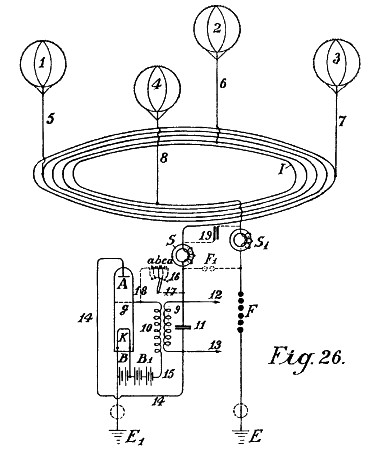
Figure 25 and 26 show modified collector balloon arrangements.
Figure 27 shows a second method of connecting conductor for the balloon aerials.
Figure 28 shows an auto-transformer method of connection.
Figure 29 shows the simplest form of construction with incandescent cathode.
Figure 30 shows a form with cigar shaped balloon.
Figure 31 is a modified arrangement.
Figure 32 shows a form with cathode and electrode enclosed in a vacuum chamber.
Figure 33 is a modified form of Figure 32.
Figure 34 shows an arc light collector.
Figure 35 shows such an arrangement for alternating current.
Figure 36 shows an incandescent collector with Nernst lamp.
Figure 37 shows a form with a gas flame.

Figure 1 illustrates a simple diagram for converting static electricity into dynamic power of a high number of oscillations. For the sake of clearness in the drawings an influence machine is assumed to be employed and not an aerial antenna. 13 and 14 are combs for collecting the static electricity of the influence machine. 7 and 8 are spark discharging electrodes. 5 and 6 are condensers, 9 an inductive primary coil, 10 secondary coil, 11 and 12 ends of conductors of the secondary coil 10. When the disc of the static influence machine is rotated by mechanical means, the combs collect the electric charges one the positive and the other the negative, and charge the condensers 5 and 6 until such a high potential is formed across the spark gap 7-8, that the spark gap is jumped. As the spark gap 7-8 forms a closed circuit with condensers 5 and 6, and inductive resistance 9, as is well known, waves of high frequency electromagnetic oscillations will pass in this circuit.
The high frequency of the oscillations produced in the primary circuit induces waves of the same periodicity in the secondary circuit. Thus in the primary circuit electromagnetic oscillations are formed by the passage of the spark over the spark gap and these waves are maintained by fresh charges of static electricity.
By suitably selecting the ratio between the number of the coils in the primary and secondary circuits with regard to a correct application of the co-efficients of resonance (especially, inductance and resistance) the high voltage of the primary circuit may be suitably converted into low voltage and high current strength.
When the oscillatory discharges in the primary circuit becomes weaker or entirely cease, the condensers are charged again by the static electricity until the accumulated charge again breaks down the spark gap. All this is repeated as long as electricity is produced by the static machine employing mechanical energy.
An elementary form of the invention is shown in Figure 2 in which two spark gaps in parallel are used one of which may be termed the working gap 7 in Figure 2, whilst the second serves as a safety device for excess voltage and consists of a larger number of spark gaps than the working section, which gaps are arranged in series and are bridged by very small capacities as is illustrated in a, b, c, Figure 2 which allow of uniform sparking in the safety section.
In Figure 2 A is the aerial antenna for collecting charges of atmospheric electricity. 13 is the earth connection of the second part of the spark gap, 5 and 6 are condensers, 9 a primary coil. Now when through the aerial A the positive atmospheric electricity seeks to combine with the negative charge to earth, this is prevented by (the air gap between) the spark gaps. The resistance of the spark gap 7 is, as shown in the drawings, lower than that of the other safety section which consists of three spark gaps connected in series, and consequently a three times greater air resistance is offered by the latter.
So long, therefore, as the resistance of the spark gap 7 is not overloaded, so that the other spark gaps have an equal resistance with it the discharges take place only over spark gap 7. Should however the voltage be increased by and influences so that it might be dangerous for charging the condensers 5 and 6 or for the coil insulation 9 and 10 in consequence of break down, by a correct regulation of this spark gap the second spark gap can discharge free from inductive effects direct to earth without endangering the machine.
Without this second spark gap, arranged in parallel having a higher resistance than the working spark gap it is impossible to collect and render available large quantities of electrical energy.
The actions of this closed oscillation circuit consisting of spark gap 7, two condensers 5 and 6, primary coil 9, and also secondary coil 10 is exactly the same as the one described in Figure 1 with the arrangement of the static induction machine with the only difference that here the second spark gap is provided. The electromagnetic high frequency alternating current obtained can be tapped off from the conductors 11 and 12 for lighting and heating purposes. Special kinds of motors adapted for working with these peculiar electrical charges may be connected at 14 and 15 which can work with static electricity charges or with high frequency oscillations.
In addition to the use of spark gaps in parallel a second measure of security is also necessary for taking off the current. This precaution consists according to this invention, in the introduction of and method of connecting certain protective electromagnets or choking coils in the aerial circuit as shown by S in Figure 3.
A single electromagnet only having a core of the thinnest possible separate laminations is connected with the aerial.
In the case of high voltages in the aerial network or at places where there are frequent thunder storms, several such magnets may however be connected in series.
In the case of large units or plants several electromagnets can be employed in parallel or in series parallel.
The windings of these electromagnets may be simply connected in series with the aerials. In this case the winding preferably consists of several thin parallel wires, which make up together, the necessary section.
The winding may be made of primary and secondary windings in the form of a transformer. The primary windings will be then connected in series with the aerial network, and the secondary winding more or less short-circuited over a regulating resistance or an induction coil. In the latter case it is possible to regulate to a certain extent the effect of the choking coils. In the further description of the connecting and constructional diagrams the aerial electromagnet choke coil is indicated by a simple ring S.

Figure 3 shows the simplest way of converting atmospheric electricity into electromagnetic wave energy by the use of special motors adapted for high oscillatory currents or static charges of electrical energy. Recent improvements in motors for working with static charges and motors working by resonance, that is to say, having groups of tuned electromagnetic cooperating circuits render this possible but such do not form part of the present invention.
A motor adapted to operate with static charges will for the sake of simplicity be diagrammatically indicated by the two semicircles 1 and 2 and the rotor of the motor by a ring M (Figure 3). A is a vertical aerial or aerial network. S the safety choke or electromagnet with coil O as may be seen is connected with the aerial A. Adjacent the electromagnet S the aerial conductor is divided into three circuits, the circuit 8 giving the safety spark gap, the circuit 7 with the working spark gap, and then a circuit including the stator terminal 1, the rotor and stator terminal 2 at which a connection is made to the earth wire. The two spark gaps are also connected metallically with the earth wire. The method of working these diagrams is as follows:
The positive atmospheric electric charge collected tends to combine with the negative electricity (or earth electricity) connected with the earth wire. It travels along the aerial A through the electromagnet S without begin checked as it flows in the same direction as the direct current. Further, its progress is arrested by two sparks gaps placed in the way and the stator condenser surfaces. The stator condenser surfaces are charged until the charge is greater than the resistance of the spark gap 7, whereupon a spark springs over the spark gap 7 and an oscillatory charge is obtained as by means of the motor M, stator surfaces 1 and 2, and spark gap 7, a closed oscillation circuit is obtained for producing the electromagnetic oscillations. The motor here forms the capacity and the necessary inductance and resistance, which, as is well known, are necessary for converting static electricity into electromagnetic wave energy.
The discharge formed are converted into mechanical energy in special motors and cannot reach the aerial network by reason of the electromagnet or choke. If, however, when a spark springs over the spark gap 7 a greater quantity of atmospheric electricity tends to flow to earth, a counter voltage is induced in the electromagnet, which is greater the more rapidly and strongly the flow of current direct to the earth is. By the formation of this opposing voltage a sufficiently high resistance is offered to the flow of atmospheric electricity direct to earth to prevent a short circuit with the earth.
The circuit containing spark gap 8 having a different wave length which is not in resonance with the natural frequency of the motor, does not endanger the motor and serves as security against excess voltage, which, as practical experiments have shown, may still arise in certain cases, but can be conducted direct to earth through this spark gap.
In the diagram illustrated in Figure 4 the spark gap 7 is shunted across condensers 5 and 6 from the motor M. This construction affords mainly a better insulation of the motor against excess voltage and a uniform excitation through the spark gap 7.
In Figure 5 a diagram is illustrated for transforming large current strengths which may be employed direct without motors, for example, for lighting or heating purposes. The main difference is that here the spark gap consists of as star shaped disk 7 which can rotate on its own axis and is rotated by a motor opposite similarly fitted electrodes 7a. When separate points of stars face one another, discharges take place, thus forming an oscillation circuit over condensers 5 and 6, and inductance 9 for oscillatory discharges. It is evident that a motor may also be directly connected to the ends of the spiral 9.
The construction of the diagram shown in Figure 6 permits of the oscillation circuit of the motor being connected with an induction coil/ Here a regulating inductive resistance is introduced for counter-acting excess voltages in the motor. By cutting the separate coils 9 (coupled inductively to the aerial) in or out the inductive action on the motor may be more or less increased or variable aerial action may be exerted on the oscillation circuit.

In Figure 7 the oscillation circuit is closed through the earth (E and E1). The spark gap 7 may be prolonged or shortened by more or fewer spark gaps being successively connected by means of a contact arm 7b.
Diagram 8 shows a unipolar connection of the motor with the aerial network. Here two oscillation circuits are closed through the same motor. The first oscillation circuit passes from aerial A through electromagnet S, point x, inductance 9a to the earth condenser 6 and further, over spark gap 7 to the aerial condenser 5 and back to x. The second oscillation circuit starts from the aerial condenser 5 at the point x1 over the inductance 9 to the earth condenser 6 at the point x3 and through the condenser 6 over the spark gap 7 back to x1. The motor itself is inserted between the two points of the spark gap 7. From this arrangement slightly damped oscillation wave currents are produced.
In the diagram illustrated in Figure 9 a loosely coupled system of connections is illustrated which is assumed to be for small motors for measuring purposes. A indicates the aerial conductor, S the electromagnet in the aerial conductor, 9 the inductance, 7 the spark gap, 5 and 6 condensers, E the earth, M the motor, and 1 and 2 stator connections of the motor. The motor is directly metallically connected with the oscillation circuit.
In Figure 10 a purely inductive coupling is employed for the motor circuit. The motor is connected with the secondary wire 10 as may be seen in Figure 11 in a somewhat modified diagram connection. The same applies to the diagram of Figure 12.
The diagrams hitherto described preferably allow of motors of small and medium strength to be operated. For large aggregates, however, they are too inconvenient as the construction of two or more oscillation circuits for large amounts of energy is difficult; the governing is still more difficult and the danger in switching on or off is greater.
A means of overcoming such difficulties is shown in Figure 13. The oscillation circuit here runs starting from the point x over condenser 5, variable inductance 9, spark gap 7, and the two segments (3a and 4a) forming arms of a Wheatstone bridge, back to x, If the motor is connected by brushes 3 and 4 transversely to the two arms of the bridge as shown in the drawings, electromagnetic oscillations of equal sign are induced in the stator surfaces 1 and 2 and the motor does not revolve. If however the brushes 3 and 4 are moved in common with the conducting wires 1 and 2 which connect the brushes with the stator poles a certain alteration or displacement of the polarity is obtained and the motor commences to revolve.
The maximum action will result if one brush 3 comes on the central sparking contact 7 and the other brush 4 on the part x. They are however, usually in practice not brought on the central contact 7 but only held in the path of the bridge segments 4a and 3a in order not to connect the spark gaps with the motor oscillation circuit.

As however, the entire oscillation energy can thereby not act on the motor it is better to carry out the same system according to the diagram 14. The diagram 14 differs from the foregoing only by the motor not being directly metallically connected with the segments of the commutator, but only a primary coil 9 which induces in a secondary coil 10, current which feeds the motor M and takes the place of the rotor. By this arrangement a good transforming action is obtained, a loose coupling and also an oscillation circuit without a spark gap.
In Figure 15 the motor is not purely inductive as in 14, but directly metallically branched off from the primary coil (at x and x1) after the principle of the auto-transformer.
In Figure 16 instead of an inductance a condenser 6 is in similar manner, and for the same object inserted between the segments 3a and 4a. This has the advantage that the segments 3a and 4a need not be made of solid metal but may consist of spiral coils whereby a more exact regulation is possible and further motors of high inductance may be employed.
The arrangements of Figures 17, 18 and 19 may be employed for use with resonance and particularly with induction condenser motors; between the large stator induction condenser surfaces, small reversing pole condenser surfaces, mall reversing pole condensers are connected, which, as may be seen from Figures 17, 18 and 19 are led together to earth. Such reversing poles have the advantage that with large quantities of electrical energy the spark formation between the separate oscillation circuits ceases.
Figure 19 shows a further method which prevents electromagnetic oscillations of high number of alternations formed in the oscillation circuit striking back to the aerial conductor. It is based on the well known principle that a mercury lamp, one electrode of which is formed of mercury, the other of solid metal such as steel allows an electric charge to pass in only one direction from the mercury to the steel and not vice versa. The mercury electrode of the vacuum tube N is therefore connected with the aerial conductor and the steel electrode with the oscillation circuit. From this it results that charges can pass only from the aerial through the vacuum tube to the oscillation circuit, but not vice versa. Oscillations which are formed on being transformed in the oscillation circuit cannot pass to the aerial conductor.
In practice these vacuum tubes must be connected behind an electromagnet as the latter alone affords no protection against the danger of lightning.
As regards the use of spark gaps, all arrangements as used for wireless telegraphy may be used. Of course the spark gaps in large machines must have a sufficiently large surface. In very large stations they are cooled in liquid carbonic acid or better still in liquid nitrogen or hydrogen; in most cases the cooling may also take place by means of liquefied low homologues of the metal series or by means of hydrocarbons the freezing point of which lies at between –90° C and –40° C. The spark gap casing must also be insulated and be of sufficient strength to be able to resist any pressure which may arise. Any undesirable excess super-pressure which may be formed must be automatically let off. I have employed wit very good results mercury electrodes which were frozen in liquid carbonic acid, the cooling being maintained during the operation from the outside through the walls.
Figure 20 is one of the simplest forms of construction of an aerial network in combination with collectors, transformers and the like illustrated diagrammatically. E is here the earth wire, 8 the safety spark gap, 7 the working spark gap, 1 and 2 the stator surfaces of the motor, 5 a condenser battery, S the protective magnet which is connected with the coil in aerial conductor, A1 to A10 aerial antennae with collecting balloons, N horizontal collecting or connecting wire from which, to the center a number of connections run.
The actual collectors consist of metal sheaths preferably made of an aluminum magnesium alloy, and are filled with hydrogen or helium and are attached t copper plated steel wires. The size of the balloon is selected so that the actual weight of the balloon and the weight of the conducting wire is supported thereby. On top of the balloon aluminum spikes, made and gilded in a special manner hereinafter described, are arranged in order to produce a conductor action. Small quantities of radium preparations, more particularly polonium-ionium or meso-thorium preparations considerably increase the ionization, and therewith the action of these collectors.
In addition to metal balloons, fabric balloons which are superficially metal coated according to Schoop’s metal spraying process, may also be employed. A metallic surface may also me produced by lacquering with metallic bronzes, preferably according to Schoop’s spraying process or lacquering with metallic bronze powders in two electrical series of widely different metals, because thereby the collecting effect is considerably increased.
Instead of the ordinary round balloons, elongated cigar shaped ones may be employed. In order also to utilize the frictional energy of the wind, patches or strips of non-conducting substances which produce electricity by friction, may be attached to the metalized balloon surfaces. The wind will impart a portion of its energy in the form of frictional electricity, to the balloon casing, and thereby the collecting effect is substantially increased.
In practice however, very high towers (up to 300 meters is fully admissible) may be employed as antennae. In these towers copper tubes rise freely further above the top of the tower. A gas lamp secured against the wind is then lit at the point of the copper tube and a netting is secured to the copper tube over the flame of this lamp to form a collector. The gas is conveyed through the interior of the tube up to the summit. The copper tube must be absolutely protected from moisture at the place at which it enters the tower and also rain must be prevented running down the walls of the tower which might lead to a bad catastrophe. This is done by bell shaped enlargements which expand downwards, being arranged in the tower in the form of high voltage insulators of Siamese pagodas.
Special attention must be devoted to the foundations of such towers. They must be well insulated from the ground, which may be obtained by first embedding a layer of concrete in a box form to a sufficient depth in the ground and inserting in this an asphalt lining and then glass bricks cast about 1 or 2 meters in thickness. Over this in turn there is a ferro-concrete layer in which alone the metal foot of the tube is secured. This concrete block must be at least 2 meters from the ground and be fully protected at the sides by a wooden covering, from moisture. In the lower part of the tower a wood or glass house for the large condenser batteries or for the motors may be constructed. In order to lead the earth connection to the ground water, a well insulated pit constructed of vitreous brick, must be provided. Several such towers are erected at equal distances apart and connected with a horizontal conductor. The horizontal connecting wires may either run directly from tower to tower or be carried on bell shaped insulators similar to those in use for high voltage conductors. The width of the network may be of any suitable size and the connection of the motors can take place at any suitable places.

In order to collect large quantities of electricity with few aerials it is well to provide the aerial conductor with batteries of condensers as shown in Figures 21 and 22. In Figure 21 the batteries of condensers 5 are connected on the one hand with the aerial electricity collectors Z by the aerial conductor A, and on the other hand interconnected in series with an annular conductor from which horizontal conductors run to the connecting points C to which the earth wire is connected.
Figure 22 shows a similar arrangement, Should two such series of antennae rings be shown by a voltmeter to have a large difference of potential (for example, one in the mountains and one in the plain) or even of different polarity these differences may be compensated for by connecting sufficiently large condenser batteries (5, 5a, 5b) by means of Maji star conductors D and D1. In Figure 23 a connection of three such rings of collectors to form a triangle with a central condenser battery is illustrated.
The condenser batteries of such large installations must be embedded in liquid gases or in liquids freezing at very low temperatures. In such cases a portion of the atmospheric energy must be employed for liquefying these gases. It is also preferable to employ pressure. By this means the condenser surfaces may be diminished, and still allow for large quantities of energy to be stored, secure against breakdown. For smaller installation the immersing of the condensers in well-insulated oil or the like, suffices. Solid substances on the other hand cannot be employed as insulators.
I wonder if our resident patent expert, Mr RedneckGoober will consider this is sufficiently detailed?
NOTE - if you want to see the diagrams, click the link above.
US Patent # 1,540,998
Conversion of Atmospheric Electric Energy
( 9 June 1925 )
Hermann PLAUSON
Be it known that I, Hermann Plauson, Estonian subject, residing in Hamburg, Germany, have invented certain new and useful improvements in the Conversion of Atmospheric Electric Energy, of which the following is a specification.
Methods of obtaining atmospheric electricity by means of metallic nettings set with spikes which are held by means of ordinary or anchored kite balloons made of fabric and filled with hydrogen, are in theory already known. Atmospheric electricity obtained in this way has been suggested to be used in the form of direct current for the charging of accumulators. This knowledge however is at present only theoretical as the conversion in practice has hitherto been a failure. No means are known of protecting the apparatus from destruction by lightning. The balloons used for collecting the charge must also me be made of very large size in order to be able to support the weight of the metallic netting and the heavy cable connections.
Instead of using heavy metallic netting as collectors attached to single air ballons of non-conducting materials which are liable to be torn and are permeable to the gas, it is proposed to use metallic balloon collectors which have the following important advantages ---
(a) The metallic cases are impenetrable to helium and hydrogen; they also represent large metallic weather-proof collecting surfaces.
(b) Radio active means the like may be easily applied internally or externally; whereby the ionization is considerable increased and therewith also the quantity of atmospheric electricity capable of being collected.
(c) Such balloon collectors of light metal do not require to be of large size as they have to carry only their own moderate weight, and that of the conducting cable or wire.
(d) The entire system therefore offers little surface for the action of storm and wind and is resistant and stable.
(e) Each balloon can be easily raised and lowered by means of a winch so that all repairs, recharging and the like can be carried out without danger during the operation.
It is further proposed to use a collecting aerial network of several separate collectors spread out in the air above the earth, which collectors are interconnected by electrical conductors.
According to this invention charges of atmospheric electricity are not directly converted into mechanical energy, and this forms the main difference from previous inventions, but the static electricity which runs to earth through aerial conductors in the form of direct current of very high voltage and low current strength is converted into electro-dynamic energy in the form of high frequency vibrations. Many advantages are thereby obtained and all disadvantages avoided.
The very high voltage of static electricity of a low current strength can be converted by this invention to voltages more suitable for technical purposes and of greater strength. By the use of closed oscillatory circuits it is possible to obtain electromagnetic waves of various amplitude and thereby to increase the degree of resonance of such current. Such resonance allows various values of inductance to be chosen whereby again the governing of the starting and stopping of machines driven thereby by simply tuning the resonance between coils of the machine and the transformer circuit forming the resonance can easily be obtained. Further, such currents have the property of being directly available for various uses, even without employing them for driving motors, of which there may be particularly mentioned, lighting, production of heat and use in electro-chemistry.
Further, with such currents a series of apparatus may be fed without direct current supply through conductors and also the electro-magnetic high frequency currents may be converted by means of special motors adapted for electro-magnetic oscillations into mechanical energy, or finally converted by special machines into alternating current of low frequency or even into direct current of high potential.
The invention is more particularly described with reference to the accompanying diagrams in which: ---
Figure 1 is and explanatory figure.
Figure 2 is a diagrammatic view of the simplest form.
Figure 3 shows a method of converting atmospheric electrical energy for use with motors.
Figure 4 is a diagram showing the use of protective means.
Figure 5 is a diagram of an arrangement for converting large current strengths.
Figure 6 is a diagram of an arrangement including controlling means.
Figure 7 shows means whereby the spark gap length can be adjusted.
Figure 8 shows a unipolar connection for the motor.
Figure 9 shows a weak coupled system suitable for use with small power motors.
Figures 10, 11, and 12 show modified arrangements.
Figure 13 shows a form of inductive coupling for the motor circuit.
Figure 14 is a modified form of Figure 13 with inductive coupling.
Figure 15 is an arrangement with non-inductive motor.
Figure 16 is an arrangement with coupling by condenser.
Figure 17, 18, and 19 are diagrams of further modifications.
Figure 20 shows a simple form in which the serial network is combined with special collectors.
Figure 21 shows diagrammatically an arrangement suitable for collecting large quantities of energy.
Figure 22 is a modified arrangement having two rings of collectors.
Figure 23 shows the connection for three rings of collectors.
Figure 24 shows a collecting balloon and diagram of its connection of condenser batteries.
Figure 25 and 26 show modified collector balloon arrangements.
Figure 27 shows a second method of connecting conductor for the balloon aerials.
Figure 28 shows an auto-transformer method of connection.
Figure 29 shows the simplest form of construction with incandescent cathode.
Figure 30 shows a form with cigar shaped balloon.
Figure 31 is a modified arrangement.
Figure 32 shows a form with cathode and electrode enclosed in a vacuum chamber.
Figure 33 is a modified form of Figure 32.
Figure 34 shows an arc light collector.
Figure 35 shows such an arrangement for alternating current.
Figure 36 shows an incandescent collector with Nernst lamp.
Figure 37 shows a form with a gas flame.
Figure 1 illustrates a simple diagram for converting static electricity into dynamic power of a high number of oscillations. For the sake of clearness in the drawings an influence machine is assumed to be employed and not an aerial antenna. 13 and 14 are combs for collecting the static electricity of the influence machine. 7 and 8 are spark discharging electrodes. 5 and 6 are condensers, 9 an inductive primary coil, 10 secondary coil, 11 and 12 ends of conductors of the secondary coil 10. When the disc of the static influence machine is rotated by mechanical means, the combs collect the electric charges one the positive and the other the negative, and charge the condensers 5 and 6 until such a high potential is formed across the spark gap 7-8, that the spark gap is jumped. As the spark gap 7-8 forms a closed circuit with condensers 5 and 6, and inductive resistance 9, as is well known, waves of high frequency electromagnetic oscillations will pass in this circuit.
The high frequency of the oscillations produced in the primary circuit induces waves of the same periodicity in the secondary circuit. Thus in the primary circuit electromagnetic oscillations are formed by the passage of the spark over the spark gap and these waves are maintained by fresh charges of static electricity.
By suitably selecting the ratio between the number of the coils in the primary and secondary circuits with regard to a correct application of the co-efficients of resonance (especially, inductance and resistance) the high voltage of the primary circuit may be suitably converted into low voltage and high current strength.
When the oscillatory discharges in the primary circuit becomes weaker or entirely cease, the condensers are charged again by the static electricity until the accumulated charge again breaks down the spark gap. All this is repeated as long as electricity is produced by the static machine employing mechanical energy.
An elementary form of the invention is shown in Figure 2 in which two spark gaps in parallel are used one of which may be termed the working gap 7 in Figure 2, whilst the second serves as a safety device for excess voltage and consists of a larger number of spark gaps than the working section, which gaps are arranged in series and are bridged by very small capacities as is illustrated in a, b, c, Figure 2 which allow of uniform sparking in the safety section.
In Figure 2 A is the aerial antenna for collecting charges of atmospheric electricity. 13 is the earth connection of the second part of the spark gap, 5 and 6 are condensers, 9 a primary coil. Now when through the aerial A the positive atmospheric electricity seeks to combine with the negative charge to earth, this is prevented by (the air gap between) the spark gaps. The resistance of the spark gap 7 is, as shown in the drawings, lower than that of the other safety section which consists of three spark gaps connected in series, and consequently a three times greater air resistance is offered by the latter.
So long, therefore, as the resistance of the spark gap 7 is not overloaded, so that the other spark gaps have an equal resistance with it the discharges take place only over spark gap 7. Should however the voltage be increased by and influences so that it might be dangerous for charging the condensers 5 and 6 or for the coil insulation 9 and 10 in consequence of break down, by a correct regulation of this spark gap the second spark gap can discharge free from inductive effects direct to earth without endangering the machine.
Without this second spark gap, arranged in parallel having a higher resistance than the working spark gap it is impossible to collect and render available large quantities of electrical energy.
The actions of this closed oscillation circuit consisting of spark gap 7, two condensers 5 and 6, primary coil 9, and also secondary coil 10 is exactly the same as the one described in Figure 1 with the arrangement of the static induction machine with the only difference that here the second spark gap is provided. The electromagnetic high frequency alternating current obtained can be tapped off from the conductors 11 and 12 for lighting and heating purposes. Special kinds of motors adapted for working with these peculiar electrical charges may be connected at 14 and 15 which can work with static electricity charges or with high frequency oscillations.
In addition to the use of spark gaps in parallel a second measure of security is also necessary for taking off the current. This precaution consists according to this invention, in the introduction of and method of connecting certain protective electromagnets or choking coils in the aerial circuit as shown by S in Figure 3.
A single electromagnet only having a core of the thinnest possible separate laminations is connected with the aerial.
In the case of high voltages in the aerial network or at places where there are frequent thunder storms, several such magnets may however be connected in series.
In the case of large units or plants several electromagnets can be employed in parallel or in series parallel.
The windings of these electromagnets may be simply connected in series with the aerials. In this case the winding preferably consists of several thin parallel wires, which make up together, the necessary section.
The winding may be made of primary and secondary windings in the form of a transformer. The primary windings will be then connected in series with the aerial network, and the secondary winding more or less short-circuited over a regulating resistance or an induction coil. In the latter case it is possible to regulate to a certain extent the effect of the choking coils. In the further description of the connecting and constructional diagrams the aerial electromagnet choke coil is indicated by a simple ring S.
Figure 3 shows the simplest way of converting atmospheric electricity into electromagnetic wave energy by the use of special motors adapted for high oscillatory currents or static charges of electrical energy. Recent improvements in motors for working with static charges and motors working by resonance, that is to say, having groups of tuned electromagnetic cooperating circuits render this possible but such do not form part of the present invention.
A motor adapted to operate with static charges will for the sake of simplicity be diagrammatically indicated by the two semicircles 1 and 2 and the rotor of the motor by a ring M (Figure 3). A is a vertical aerial or aerial network. S the safety choke or electromagnet with coil O as may be seen is connected with the aerial A. Adjacent the electromagnet S the aerial conductor is divided into three circuits, the circuit 8 giving the safety spark gap, the circuit 7 with the working spark gap, and then a circuit including the stator terminal 1, the rotor and stator terminal 2 at which a connection is made to the earth wire. The two spark gaps are also connected metallically with the earth wire. The method of working these diagrams is as follows:
The positive atmospheric electric charge collected tends to combine with the negative electricity (or earth electricity) connected with the earth wire. It travels along the aerial A through the electromagnet S without begin checked as it flows in the same direction as the direct current. Further, its progress is arrested by two sparks gaps placed in the way and the stator condenser surfaces. The stator condenser surfaces are charged until the charge is greater than the resistance of the spark gap 7, whereupon a spark springs over the spark gap 7 and an oscillatory charge is obtained as by means of the motor M, stator surfaces 1 and 2, and spark gap 7, a closed oscillation circuit is obtained for producing the electromagnetic oscillations. The motor here forms the capacity and the necessary inductance and resistance, which, as is well known, are necessary for converting static electricity into electromagnetic wave energy.
The discharge formed are converted into mechanical energy in special motors and cannot reach the aerial network by reason of the electromagnet or choke. If, however, when a spark springs over the spark gap 7 a greater quantity of atmospheric electricity tends to flow to earth, a counter voltage is induced in the electromagnet, which is greater the more rapidly and strongly the flow of current direct to the earth is. By the formation of this opposing voltage a sufficiently high resistance is offered to the flow of atmospheric electricity direct to earth to prevent a short circuit with the earth.
The circuit containing spark gap 8 having a different wave length which is not in resonance with the natural frequency of the motor, does not endanger the motor and serves as security against excess voltage, which, as practical experiments have shown, may still arise in certain cases, but can be conducted direct to earth through this spark gap.
In the diagram illustrated in Figure 4 the spark gap 7 is shunted across condensers 5 and 6 from the motor M. This construction affords mainly a better insulation of the motor against excess voltage and a uniform excitation through the spark gap 7.
In Figure 5 a diagram is illustrated for transforming large current strengths which may be employed direct without motors, for example, for lighting or heating purposes. The main difference is that here the spark gap consists of as star shaped disk 7 which can rotate on its own axis and is rotated by a motor opposite similarly fitted electrodes 7a. When separate points of stars face one another, discharges take place, thus forming an oscillation circuit over condensers 5 and 6, and inductance 9 for oscillatory discharges. It is evident that a motor may also be directly connected to the ends of the spiral 9.
The construction of the diagram shown in Figure 6 permits of the oscillation circuit of the motor being connected with an induction coil/ Here a regulating inductive resistance is introduced for counter-acting excess voltages in the motor. By cutting the separate coils 9 (coupled inductively to the aerial) in or out the inductive action on the motor may be more or less increased or variable aerial action may be exerted on the oscillation circuit.
In Figure 7 the oscillation circuit is closed through the earth (E and E1). The spark gap 7 may be prolonged or shortened by more or fewer spark gaps being successively connected by means of a contact arm 7b.
Diagram 8 shows a unipolar connection of the motor with the aerial network. Here two oscillation circuits are closed through the same motor. The first oscillation circuit passes from aerial A through electromagnet S, point x, inductance 9a to the earth condenser 6 and further, over spark gap 7 to the aerial condenser 5 and back to x. The second oscillation circuit starts from the aerial condenser 5 at the point x1 over the inductance 9 to the earth condenser 6 at the point x3 and through the condenser 6 over the spark gap 7 back to x1. The motor itself is inserted between the two points of the spark gap 7. From this arrangement slightly damped oscillation wave currents are produced.
In the diagram illustrated in Figure 9 a loosely coupled system of connections is illustrated which is assumed to be for small motors for measuring purposes. A indicates the aerial conductor, S the electromagnet in the aerial conductor, 9 the inductance, 7 the spark gap, 5 and 6 condensers, E the earth, M the motor, and 1 and 2 stator connections of the motor. The motor is directly metallically connected with the oscillation circuit.
In Figure 10 a purely inductive coupling is employed for the motor circuit. The motor is connected with the secondary wire 10 as may be seen in Figure 11 in a somewhat modified diagram connection. The same applies to the diagram of Figure 12.
The diagrams hitherto described preferably allow of motors of small and medium strength to be operated. For large aggregates, however, they are too inconvenient as the construction of two or more oscillation circuits for large amounts of energy is difficult; the governing is still more difficult and the danger in switching on or off is greater.
A means of overcoming such difficulties is shown in Figure 13. The oscillation circuit here runs starting from the point x over condenser 5, variable inductance 9, spark gap 7, and the two segments (3a and 4a) forming arms of a Wheatstone bridge, back to x, If the motor is connected by brushes 3 and 4 transversely to the two arms of the bridge as shown in the drawings, electromagnetic oscillations of equal sign are induced in the stator surfaces 1 and 2 and the motor does not revolve. If however the brushes 3 and 4 are moved in common with the conducting wires 1 and 2 which connect the brushes with the stator poles a certain alteration or displacement of the polarity is obtained and the motor commences to revolve.
The maximum action will result if one brush 3 comes on the central sparking contact 7 and the other brush 4 on the part x. They are however, usually in practice not brought on the central contact 7 but only held in the path of the bridge segments 4a and 3a in order not to connect the spark gaps with the motor oscillation circuit.
As however, the entire oscillation energy can thereby not act on the motor it is better to carry out the same system according to the diagram 14. The diagram 14 differs from the foregoing only by the motor not being directly metallically connected with the segments of the commutator, but only a primary coil 9 which induces in a secondary coil 10, current which feeds the motor M and takes the place of the rotor. By this arrangement a good transforming action is obtained, a loose coupling and also an oscillation circuit without a spark gap.
In Figure 15 the motor is not purely inductive as in 14, but directly metallically branched off from the primary coil (at x and x1) after the principle of the auto-transformer.
In Figure 16 instead of an inductance a condenser 6 is in similar manner, and for the same object inserted between the segments 3a and 4a. This has the advantage that the segments 3a and 4a need not be made of solid metal but may consist of spiral coils whereby a more exact regulation is possible and further motors of high inductance may be employed.
The arrangements of Figures 17, 18 and 19 may be employed for use with resonance and particularly with induction condenser motors; between the large stator induction condenser surfaces, small reversing pole condenser surfaces, mall reversing pole condensers are connected, which, as may be seen from Figures 17, 18 and 19 are led together to earth. Such reversing poles have the advantage that with large quantities of electrical energy the spark formation between the separate oscillation circuits ceases.
Figure 19 shows a further method which prevents electromagnetic oscillations of high number of alternations formed in the oscillation circuit striking back to the aerial conductor. It is based on the well known principle that a mercury lamp, one electrode of which is formed of mercury, the other of solid metal such as steel allows an electric charge to pass in only one direction from the mercury to the steel and not vice versa. The mercury electrode of the vacuum tube N is therefore connected with the aerial conductor and the steel electrode with the oscillation circuit. From this it results that charges can pass only from the aerial through the vacuum tube to the oscillation circuit, but not vice versa. Oscillations which are formed on being transformed in the oscillation circuit cannot pass to the aerial conductor.
In practice these vacuum tubes must be connected behind an electromagnet as the latter alone affords no protection against the danger of lightning.
As regards the use of spark gaps, all arrangements as used for wireless telegraphy may be used. Of course the spark gaps in large machines must have a sufficiently large surface. In very large stations they are cooled in liquid carbonic acid or better still in liquid nitrogen or hydrogen; in most cases the cooling may also take place by means of liquefied low homologues of the metal series or by means of hydrocarbons the freezing point of which lies at between –90° C and –40° C. The spark gap casing must also be insulated and be of sufficient strength to be able to resist any pressure which may arise. Any undesirable excess super-pressure which may be formed must be automatically let off. I have employed wit very good results mercury electrodes which were frozen in liquid carbonic acid, the cooling being maintained during the operation from the outside through the walls.
Figure 20 is one of the simplest forms of construction of an aerial network in combination with collectors, transformers and the like illustrated diagrammatically. E is here the earth wire, 8 the safety spark gap, 7 the working spark gap, 1 and 2 the stator surfaces of the motor, 5 a condenser battery, S the protective magnet which is connected with the coil in aerial conductor, A1 to A10 aerial antennae with collecting balloons, N horizontal collecting or connecting wire from which, to the center a number of connections run.
The actual collectors consist of metal sheaths preferably made of an aluminum magnesium alloy, and are filled with hydrogen or helium and are attached t copper plated steel wires. The size of the balloon is selected so that the actual weight of the balloon and the weight of the conducting wire is supported thereby. On top of the balloon aluminum spikes, made and gilded in a special manner hereinafter described, are arranged in order to produce a conductor action. Small quantities of radium preparations, more particularly polonium-ionium or meso-thorium preparations considerably increase the ionization, and therewith the action of these collectors.
In addition to metal balloons, fabric balloons which are superficially metal coated according to Schoop’s metal spraying process, may also be employed. A metallic surface may also me produced by lacquering with metallic bronzes, preferably according to Schoop’s spraying process or lacquering with metallic bronze powders in two electrical series of widely different metals, because thereby the collecting effect is considerably increased.
Instead of the ordinary round balloons, elongated cigar shaped ones may be employed. In order also to utilize the frictional energy of the wind, patches or strips of non-conducting substances which produce electricity by friction, may be attached to the metalized balloon surfaces. The wind will impart a portion of its energy in the form of frictional electricity, to the balloon casing, and thereby the collecting effect is substantially increased.
In practice however, very high towers (up to 300 meters is fully admissible) may be employed as antennae. In these towers copper tubes rise freely further above the top of the tower. A gas lamp secured against the wind is then lit at the point of the copper tube and a netting is secured to the copper tube over the flame of this lamp to form a collector. The gas is conveyed through the interior of the tube up to the summit. The copper tube must be absolutely protected from moisture at the place at which it enters the tower and also rain must be prevented running down the walls of the tower which might lead to a bad catastrophe. This is done by bell shaped enlargements which expand downwards, being arranged in the tower in the form of high voltage insulators of Siamese pagodas.
Special attention must be devoted to the foundations of such towers. They must be well insulated from the ground, which may be obtained by first embedding a layer of concrete in a box form to a sufficient depth in the ground and inserting in this an asphalt lining and then glass bricks cast about 1 or 2 meters in thickness. Over this in turn there is a ferro-concrete layer in which alone the metal foot of the tube is secured. This concrete block must be at least 2 meters from the ground and be fully protected at the sides by a wooden covering, from moisture. In the lower part of the tower a wood or glass house for the large condenser batteries or for the motors may be constructed. In order to lead the earth connection to the ground water, a well insulated pit constructed of vitreous brick, must be provided. Several such towers are erected at equal distances apart and connected with a horizontal conductor. The horizontal connecting wires may either run directly from tower to tower or be carried on bell shaped insulators similar to those in use for high voltage conductors. The width of the network may be of any suitable size and the connection of the motors can take place at any suitable places.
In order to collect large quantities of electricity with few aerials it is well to provide the aerial conductor with batteries of condensers as shown in Figures 21 and 22. In Figure 21 the batteries of condensers 5 are connected on the one hand with the aerial electricity collectors Z by the aerial conductor A, and on the other hand interconnected in series with an annular conductor from which horizontal conductors run to the connecting points C to which the earth wire is connected.
Figure 22 shows a similar arrangement, Should two such series of antennae rings be shown by a voltmeter to have a large difference of potential (for example, one in the mountains and one in the plain) or even of different polarity these differences may be compensated for by connecting sufficiently large condenser batteries (5, 5a, 5b) by means of Maji star conductors D and D1. In Figure 23 a connection of three such rings of collectors to form a triangle with a central condenser battery is illustrated.
The condenser batteries of such large installations must be embedded in liquid gases or in liquids freezing at very low temperatures. In such cases a portion of the atmospheric energy must be employed for liquefying these gases. It is also preferable to employ pressure. By this means the condenser surfaces may be diminished, and still allow for large quantities of energy to be stored, secure against breakdown. For smaller installation the immersing of the condensers in well-insulated oil or the like, suffices. Solid substances on the other hand cannot be employed as insulators.