Exploring the technology of Prof. Nigel Cheese: Quantum Battery

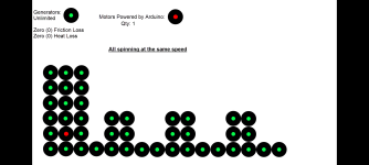
Houston we have liftoff.

The main system is pretty much built.

Now the idea is to fine tune and keep adding generators until I can get enough to dump the power bank.


Any guesses?

I also need to be more precise on speed and distances which I will have to re think.

Anyway.

All ideas and inputs welcome.. I feel like im chatting with myself a bit.... Anyway. Im still going to share.

Latest_Free_Energy_Update.mp4

-Eric
 

Attachments

  • Screenshot_20251224_193858_Gmail.png
    Screenshot_20251224_193858_Gmail.png
    352.4 KB · Views: 52
So I figured I would post the other video that I used if anyone wants to repeat.


View: https://youtu.be/7spK_BkMJys?si=VR9VV_Q9gW_CrIsO


I also remodeled the design which is on-going.

Tighter fit, less wobbles, screwed in motors with a set screw in the magnet wheels, hopefully this will allow me to reach higher voltages.

Still more testing to do.

I ordered another battery.
I am going to drain it and see how long that takes a few times by running it from a full charge.

Im also going to see how long a drained battery takes to charge using this method, a few times for an average.

Hopefully one is more than the other haha, but, I could charge 100 batteries at the same time.... or 1 million....

Anyway, Ill keep updating as I go along.

-Eric
 

Attachments

  • 20251227_102603.jpg
    20251227_102603.jpg
    1.6 MB · Views: 28
  • 20251227_102709.jpg
    20251227_102709.jpg
    968.5 KB · Views: 23
  • Screenshot_20251227_065848_Gmail.png
    Screenshot_20251227_065848_Gmail.png
    1.4 MB · Views: 29
Impressive. Your tenacity in this field far exceeds my pathetic efforts a few years back.
 
Progress...


Edit:
@AthroposRex

So what i think I may be needing some help on I'd say is going to be where I start attempting to combine currents and voltages. Best way to describe it is.... I have a penny and by the use of series and parallels, somehow increase both to usable energy.

Hopefully this picture explains it.

Cus I have no idea how to wire that stuff up....
You would want to connect them in parallel to get the most usable power. If you connect them in series you’ll get more voltage but you won’t increase the current as far as I understand, but in parallel you’ll have more current at the same voltage. To do work you need current, otherwise you may get voltage but it won’t be enough current to be useful. Charging capacitors and then using them for the work might be a way to go. Or maybe charge a battery with the caps then then use the battery to drive whatever. Voltage and current is directly proportional unless you use a step up to boost the voltage, then the current drops inversely. Wire in parallel and test what you’re getting from it. Here’s a guide on how to breadboard a parallel circuit. It’s pretty simple, instead of going to the next they all connect to input and output simultaneously. https://www.allaboutcircuits.com/textbook/direct-current/chpt-5/simple-parallel-circuits/
Because they are all more or less identical, they should synchronize. The only time it’s an issue is when they are all mismatched
So im straight up pushing 16 volts with a 12v battery pack

15.2 with 1 motor and 1 generator
15Volts.mp4

16.6 with 1 motor and 2 generators
16-Volts.mp4

Everyone asks about Amps so im in the process of hooking that up.

So far it seems to only use 0.1
 

Attachments

  • 20260126_161808.jpg
    20260126_161808.jpg
    603.6 KB · Views: 24
It seems the work of Nigel has attracted a new crowd of onlookers.
Spoiler Alert: yes that video does an excellent job at misrepresenting Nigel's discoveries. We shouldn't expect anything else.

But, you know, after watching that video, it made me appreciate the efforts that have been pooled together in this thread from all sorts of random people across this earth.

In the past I did express frustration and disappointment with this technology, and my failed efforts in decoding it, but when I let go of that and just examine this from a different view, I feel really grateful that there are men and women here who are going against the grain and discovering something new together to the best of their efforts and ability.

Thank you @Photon and @BravoSix for documenting your detailed experiments.
Thank you @MJ.nfl for helping to find lost videos and documents of Nigel's work from the past.
And thank you @3D Printing Bear for launching this thread from the very beginning.

It's been quite a ride.
 
So 2 years later I finally managed to duplicate one of Nigel's experiments, which is using 2 Earths to light up LEDs in a specific configuration.

a.png


This LED configuration does not work with a traditional DC power source. I tried powering these LEDs exactly as they are configured with a series of alkaline batteries and only one or two would light up, but not all of them at once.

I think the energy flowing through the 2 Earths is moving in two different directions at the same time. I believe the top row of LEDs visually represents this energy moving from Left to Right, and the bottom row represents its movement from Right to Left. This is based on what Nigel has said about the magnetic fields of a magnet: the energy flows "bi-directionally" and is "contra-rotating," like the threads of a bolt.

I recently watched a podcast about old world technology and one of the guests said:
...when you force positives together or negatives together... you create a "third" and they call it "the scalar."

By connecting 2 Earths to a circuit in this way, you are forcing two negatives together, or two south poles together. South does not like south, so in return you get this movement of all these south particles that are trying to get away from each other, or trying to go back home, and this movement of magnetic particles generates electricity.

I remember reading this simple equation once:

magnetism + movement = electricity​
movement + electricity = magnetism​
electricity + magnetism = movement​

Not every earth/ground connection in a house will work. The best ground connections might be in the basement.

b.png
c.png
 
Reading through the thread again I can see what @Photon said in 2022 makes a lot more sense now:
if there is an AC voltage across the LED bridge...then you have created frequency harmonics which [is what] we want, and it means that there is a reciprocating current traveling in both directions through the LED bridge.

This technology will really only make sense once you start getting hands-on experience in it.
 
So from the 2 Earths in my house I get a ground potential difference of 45 VAC. But this voltage can't just be dumped straight into a capacitor. Or, well it can, but it's extremely slow (can barely reach 1 volt in 5 minutes). That's where Nigel's Light Bridge (LB) comes in: the moment you add the LB and a FWBR to rectify the AC to DC, you can fully charge a 25V 100uF capacitor in 5 minutes. See circuit diagram below.
E1 E2 FWBR.png
But this basic setup only charges up to 30V, even if I add larger capacitors to the circuit (200V, 300V, etc).

According to Nigel, (and @Photon and @BravoSix) that 30V cap can be increased by introducing EMF to one of the Earths. For the last 3 days I've been trying to figure this out, but no luck so far.

I thought that by making a Joule Thief I could then take the oscillation frequency that exists between the Emitter and Collector (~176kHz) and somehow feed that into the LB, but it's not working no matter what combination I use.

My Joule Thief oscillates at approx. 176,000 Hz, which is technically an electromagnetic frequency, since the magnetic field is expanding and collapsing repeatedly---but maybe this oscillation isn't powerful enough?

Nigel spoke about how using the EMF from an AC inverter can be fed back into the LB circuit, causing the LB to recycle the energy continuously. I guess I assumed that since AC is only 60Hz, then a Joule Thief at 176kHz would be even better.

Maybe I just don't fully understand the nature of electromagnetic frequencies.

I've also noticed that anytime traditional electricity touches the LB, it kills the LB entirely.
 
Last edited:
But this basic setup only charges up to 30V, even if I add larger capacitors to the circuit (200V, 300V, etc).
Scratch that. The multimeter was draining most of the voltage (even though it was turned off). Once I unclipped the meter's alligator clips from the circuit I was able to charge a 450V 1000uF capacitor to 47 VDC in less than 30 minutes. It can't go above that because the ground potential difference only provides about 45VAC.

...using the EMF from an AC inverter can be fed back into the LB circuit...
I just realized that Nigel is referring to Electromotive force whenever he says "EMF"....I thought he was talking about the electromagnetic frequency...I feel a little silly now, but that's okay.

Electromotive force is also known as flyback or "back EMF."

Now I have to re-do my experiments all over again.
 
Last edited:
In the video Nigel says they are connected by 1 wire, but its 1 multicore wire. It's two wires; a serial connector and an RF signal that goes to ground and is connected at the center of each row of LEDs.
This description is a bit confusing for anyone who isn't an expert in electronics (AKA me), but I think I can translate it: It's one wire with two conductors that are separated by insulation; a bonded pair wire, like speaker wire, or the wire that comes with a DC barrel power adapter.
bonded pair wire.png
So Nigel was using:
  • 1 conductor to daisy-chain all the LED boards in series, and
  • the other conductor as a high-frequency oscillator signal carrier that sent signals straight to Ground? maybe?
bonded pair daisy chain.png
 
Last edited:
Tips
Tips
Please respect our Posting Rules.
Back
Top