Nice try but you are missing the earth connections. I have replicated some of Nigel's light bridge. Before you do anything you will need 2 earths connected to both ends of the LEDs. Iron is best, steel or galvanized steel is also good. Connect some black annealed wire to the ground and connect it to a ring of LEDs in a serial connection and keep the wire insulated or avoid the wire touching anything in between. Use 5mm clear cold white LEDs. Avoid using copper. When it's dark you should see the ring of LEDs glow white/light blue very dim and flicker. This is a Cherenkov effect. The arrangement described above will not produce power but demonstrates that LEDs really do not need much current to operate.
Well done mate. Guess who?
BravosSix apologies for the assumption that you hadn't used two earths, I couldn't see these in the picture with the Light Bridge and the oscilloscope. The voltage issue you have is with just working with a DC earth the LEDs are limiting the voltage output. For example you have sixteen 10mm LEDs and only getting 29V. So on average it is generating 29 V / 16 LEDs or approx. 1.8V per LED. Well done. To get the higher voltage across the capacitor a high frequency signal and a serial LED load is needed. Nigel mentions in other videos that a DC to AC inverter is used on the capacitor output. The frequency is returned to one earth to create harmonic frequencies across the light bridge.
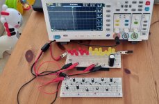
The 1st image is my breadboard R&D version of the photonic harvester's light bridge. On the bottom left are two magnetic compound SIPs and a twin earthed Cherenkov LED ring. All LEDs are warm white piranha / super flux LEDs. Above that is a magnetic convergence circuit. In the center and bottom right are the LED load panels and capacitors for storage. At the top right is the frequency management unit microprocessor. Note that the setup below was just for temporary testing and does not reflect the current design.
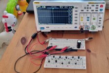
The 2nd image shows Nigel's LED load panels from the videos found on Greg Ottenmeyer's Gaea ZPE youtube channel. I contacted Nigel and asked about these and he suggested that these panels are just 48 LEDs in series. In the video Nigel says they are connected by 1 wire, but its 1 multicore wire. It's two wires; a serial connector and an RF signal that goes to ground and is connected at the center of each row of LEDs. These panels are not intended to go to full brightness they are used to bring up the voltage potential. These panels are similarly replicated in the top image using 8 rows of 16 LEDs in parallel which gives a voltage of 48V. The parallel connections increases the current.
Has anyone tried connecting multiple QB stacks in parallel? I've read that many of you are getting great voltage potentials whilst increasing the length of the stacks, but just like the LED load panels I described previously that are used in Nigel's light bridge, adding QB stacks in parallel would increase the current output. I would like to hear if anyone can increase the brightness of their LEDs or even store the harvested energy into capacitors. For QB technology to be viable it would need to store the harvested energy into supercapacitors at 5V or 12V or more.