flourisheric
Contributor
- Joined
- Feb 10, 2023
- Messages
- 30
- Reaction score
- 49
Hi,
I am new.
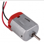
I was creepin, I bought all the materials... and it works!
3d print bear you rock!
I saw Nigels video but never gave it any thought to trying it myself. That is.. until i saw your video. You seemed like a regular guy deciding to try it, Nigels kind of seemed off for some reason.... but you convinced me to buy the stuff and give it a shot. And I am glad I did.
There is a huge potential with this.
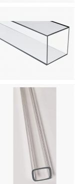
I love the acrylic. Idea for the water.
I had a question/ idea..
.
What if.... we put a large number of connected magnet sandwiches inside of a plastic bin, cut 2 holes for the leads and seal it so only the magnet can be touched from outside, then filled the bin with distilled water?
Would that work?
Also I am curious of inverters and capacitors... but I am. Ot that great with circuits. Hope to learn more.
Thanks for the head rush of awesome!
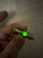
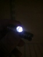
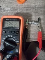
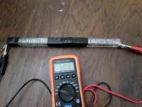
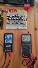
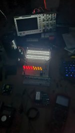
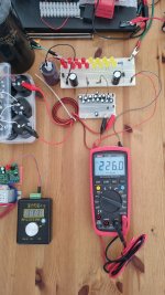
Here's my result so far
I am new.
I was creepin, I bought all the materials... and it works!
3d print bear you rock!
I saw Nigels video but never gave it any thought to trying it myself. That is.. until i saw your video. You seemed like a regular guy deciding to try it, Nigels kind of seemed off for some reason.... but you convinced me to buy the stuff and give it a shot. And I am glad I did.
There is a huge potential with this.
I love the acrylic. Idea for the water.
I had a question/ idea..
.
What if.... we put a large number of connected magnet sandwiches inside of a plastic bin, cut 2 holes for the leads and seal it so only the magnet can be touched from outside, then filled the bin with distilled water?
Would that work?
Also I am curious of inverters and capacitors... but I am. Ot that great with circuits. Hope to learn more.
Thanks for the head rush of awesome!
Here's my result so far
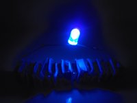


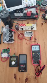


 Gotta order some more one of these days...