Exploring the technology of Prof. Nigel Cheese: Quantum Battery

I've been searching and trying different electrolytes because I believe that is the secret to make this work.

I've tried several and specially one that reduces magnesium corrosion and the voltage is interesting, it improves with temperature.

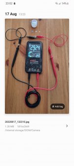
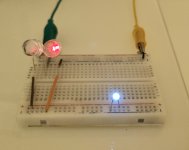
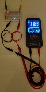
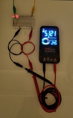
It's a simple mix: 5ml glycerine with 1 tea spoon of Epsom Salt. You can add more Epsom Salt and try it out. Heat the glycerine to mix it with the Epsom salt. If your positive is the pyrolytic graphite and the negative the magnesium your volt will be around 1.92 volts in that electrolyte. I'm sure it can be optimised.

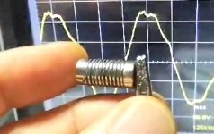
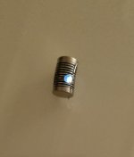
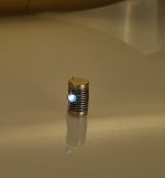
Configuration of the QB:

[ 10x0.5 mm Magnet , 0.8x0.3mm Pyrolytic Graphite , 0.8mm paper with one droplet of the electrolyte on the magnesium side, magnesium , magnet ]

At this moment I'm using the magnesium strips cut in several to fill the 8mm circle paper, that's what I have at the moment , but I want to get a thin magnesium plate to replace it with the strips.

I'm not using any copper nor zinc as they seem to reduce the voltage by alot and they suffer from oxidation destroying the magnets.
The idea is to not use any water so the magnesium don't suffer fast corrosion.

I'm also using car engine oil to protect my magnets from corrosion and there is no influence on the voltage. The oil is not conductive nor blocks the ions movement in the configuration.

Any one have similar experience that want to share?
 
Just got to playing around with this today

I have six 1/8”x1/2”x1/2” gold plated N52 magnets
The stack is mag, copper, salt water soaked paper, zinc, mag.

This produced 500-600 mv

I changed to a salt water soaked wafer of aromatic cedar(from a different project) approx half a mm thick
With all six magnets used we got 3.7-3.8volts.

Adding an extra magnet on either end of the cell did not increase the voltage. Adding two more copper and zinc wafers per cell did not give more voltage either.

This seems to work!!! Now to work on how many amps and the long term effects of galvanic corrosion.
Instead of water and salt try glycerine mixed with magnesium sulfate or Epsom Salt and instead of zinc try magnesium. You will get better volts and less corrosion. The next step is replace copper with pyrolytic graphite that is way more conductive than copper.

I would try silver but I don't have it like that.

The electrolyte used in between the magnets can make a difference.

I'm also on electrolyte research to obtain the best I can. So far I got one that gives 2.1 volts but drops. Trying to understand how to make it stable with that voltage.

I know there are some that were able to create a Ionic liquid that gave 0.73 volts non change for 2 weeks. Trying to replicate but I'm waiting on materials to arrive.
20220809_234340.jpg
I'm also researching for the best electrolyte that I can to use it between the magnets in a correct way.
 
I’ve had the same meter for 25+ years. Today the dial broke off at 200V DC. I said to my buddy. If we get even one volt on that meter I’ll be happy. I was ecstatic at 3.7!! :)
 
I’ve had the same meter for 25+ years. Today the dial broke off at 200V DC. I said to my buddy. If we get even one volt on that meter I’ll be happy. I was ecstatic at 3.7!! :)
Can we have more info and details please ?
Anyone tried to use platinum in QB configuration ?

It's highly corrosive resistant in case corrosive liquids are being used.

Just adding tips.
 
Last edited:
I have a total of 2 hrs into this so I am far from knowledgeable on the subject.

That said I was lucky to meet the gentleman that was part of a team of three researching new battery tech. They ended up inventing the lithium ion battery!! This gentleman gave me an entire roll of what looks like graphite paper and another roll of carbon fibre cloth. He had a dozen rolls that he was going to throw out. “This stuff was really expensive when we bought it, but I’m moving and don’t want to take it with me.” “You want them?” Hell Ja!!!! Anyhow. I will post when I have something new to share. I have to check that I didn’t throw the graphite out. It’s been sitting in my wood shed for years. I had no idea what to use it for. I’m starting to think I may be a closet hoarder!
 
Screenshot_20220729-174825_Gallery.jpg

I would love to know what are the materials in between those magnets.

Something tells me it's not copper , paper and zinc .

Any ideas, please share.
 
I dug out a roll of this graphite paper. It came from Russia 20 years ago. Maybe some Russian speakers can translate.

23643524-BDC1-4CED-81EB-D7D9E1D87CAB.jpeg
BB79108E-2A24-4F73-B7F1-5292F368FC96.jpeg

I tried the glycerine and mag/sulfate solution on the wood wafers. Also tried it with the graphite paper I have. What worked best after many configurations was
Magnet,graphite,copper,wood,zinc graphite, copper, wood, zinc, magnet. This made 1.3V.
Using all six magnets with two sets of materials in between yielded 6.7V. I’m sure this can be optimised. I cut the pieces by hand. Some are smaller some bigger than the magnets. Also some of the wood pieces chipped. After half an hour I checked and voltage has dropped to 4.2 so there is definitely room for improvement on the electrolyte

Those pieces might be silver in between graphite? Platinum sounds a little expensive for a guy living in Croatia without an income.
 
I dug out a roll of this graphite paper. It came from Russia 20 years ago. Maybe some Russian speakers can translate.


I tried the glycerine and mag/sulfate solution on the wood wafers. Also tried it with the graphite paper I have. What worked best after many configurations was
Magnet,graphite,copper,wood,zinc graphite, copper, wood, zinc, magnet. This made 1.3V.
Using all six magnets with two sets of materials in between yielded 6.7V. I’m sure this can be optimised. I cut the pieces by hand. Some are smaller some bigger than the magnets. Also some of the wood pieces chipped. After half an hour I checked and voltage has dropped to 4.2 so there is definitely room for improvement on the electrolyte

Those pieces might be silver in between graphite? Platinum sounds a little expensive for a guy living in Croatia without an income.
Silver is more conductive than copper so it will probably increase the voltage.

How thick are the wood wafers ?
They probably last longer than the paper.

Now will be interesting to see how long the configuration last. Normally it's created 10 cell configuration or 13 cell.

My 6 cell version is returning 9v but the voltage drops slowly .

My research is now on a stable electrolyte.

Somilar to this but with higher voltage.
This guy made an ionic liquid electrolyte that produces 0.73 volts but after 2 weeks it remained 0.73 volts.

We just need to understand what needs to be done to maintain the electrolyte voltage.


View: https://youtu.be/-zOVghapM2A

Screenshot_20220814-221947_Gallery.jpg
 
Thank you for your pictures. Good work
That's one big thick cell indeed.

My goal is to make it more compressed like Nigel did but with 2.4 volts each cell.

I'm still researching the best way how to achieve it through different materials or different improved electrolyte.

I strongly believe there are dry materials that will make it possible without continuous moisture the construction.

Screenshot_20220815-083701_Gallery.jpg
 
I did some more playing around with this. Seems magnets are optional. I’m getting the same on the meter with or without the magnets Stack of copper paper zinc ad infinatum
0CEC68D0-606E-484B-8AAF-B1D5BA88A49A.jpeg
power out of stack w no magnets
AAD26A09-3B31-4E51-8C25-7F959119A751.jpeg
 
I did some more playing around with this. Seems magnets are optional. I’m getting the same on the meter with or without the magnets Stack of copper paper zinc ad infinatum power out of stack w no magnets
That's probably because you are using the electrolyte.

The main post by Calebc shows there is voltage with distilled water and no extra ingredients. Does galvanic battery work with just distilled water? Not the same way.

When property built , with magnets alignment they increase the voltage. It was demonstrated in the main topic by calebc .

Until we find out the secret of the correct materials for the optimized QB , this may be an option.

Remember this video from Nigel 😉

View: https://youtu.be/rZKphUw3pQM
 

Attachments

  • Screenshot_20220729-174825_Gallery.jpg
    Screenshot_20220729-174825_Gallery.jpg
    369.6 KB · Views: 102
I ordered some materials to do some further testing. .5mm Magnesium sheet and also some pyrolitic graphite.

Using distilled could still be electrolytic depending on what it touches. The very paper itself could have enough "salts" to make it conductive. Nigel gives us a hint but doesn't always explain it for us dummies.

If we are truly converting the magnetic/aetheric energy to electricity I don't know.
 
How is it possible to have a max of 24 volts from a 10 cell QB and also comparing to a bigger one (80 cell version) also and only have 24 volts?

What Am I missing ?

If a 10 cell version can produce 24 volts, it means Nigel configuration can produce 2.4 volt per cell. I wonder if and what electrolyte was used.

If 10 cell version produces 24 volts the bigger one with 80 should not only produce 24 volts at peak.

Again : what am I missing ?
What you're seeing in that video of Nigel's is I believe the highest output per cell that Nigel has ever reached. I don't know all the details of the QB in that video, but there are several design aspects I haven't been able to apply for increase in volts-per-cell. What I'm trying to focus on more currently is making a cell that will last months if not years when properly built, and would only ever theoretically need to be re-filled, or individual cells replaced between the magnets. If a single cell that only puts out ~.8V compared to 2.4V lasts a year, then that accumulated lesser potential ads up simply because of time, which is a small part of why I'm not focused much on higher voltage per cell. I have reached 1.9V in a single cell and have photos to prove it, but the design was far more temporary. In an emergency capacity, designs that are temporary but with a higher yet shorter output can absolutely be made. I just need to not have a full-time job and homestead to have more time to develop new designs and put them out for others to try. :)
 
I ordered some materials to do some further testing. .5mm Magnesium sheet and also some pyrolitic graphite.

Using distilled could still be electrolytic depending on what it touches. The very paper itself could have enough "salts" to make it conductive. Nigel gives us a hint but doesn't always explain it for us dummies.

If we are truly converting the magnetic/aetheric energy to electricity I don't know.
Agreed .

I'm also waiting on 0.4mm magnesium sheet to change the magnesium strip peaces.

On my new 10mm x 0.5mm configuration I only use the following :

[ magnet, 0.8mm pyrolytic graphite touching north side of magnet, 0.6mm baking paper and the magnesium strip piece that must fits inside the 0.6mm baking paper. I put my DIY electrolyte in the baking paper on both sides to touch the pyrolytic graphite and the magnesium, magnet ]

I know there is room for the electrolyte improvement but this one is kinda stable and drops very very slowly. I'm researching for one that doesn't drop, also it doesn't have water so it doesn't evaporate like the ones with water, and also water destroys the magnets creating rust and oxidation.
20220817_173246.jpg
 
I left a single cell together for approx. 24hrs. Upon taking it apart the copper had blackened(corroded) where the paper was and the zinc also to a lesser degree.

I think this galvanic action makes these devices less attractive in the long run. Some kind of solid electrolyte that does not cause
corrosion but still puts out power is needed. If such a thing exists.

So far I’ve tried zinc paper wood copper and graphite paper. The graphite paper did nothing at all. Regardless of where it was placed in the cell.
The cell has voltage with or without the magnets indicating it is not the magnets providing the power. I have some silver sheet on order also. That will be interesting but I suspect it will turn black like the copper when using the magnesium sulphate electrolyte.

I think longevity and corrosion are the biggest hurdles that may or may not be overcome.

That said I had a friend that made a product called Bioshield that had some kind of free energy source in it, connected to a toroidal coil. He said it would light up an led to prove it makes power. Wish I still had it but I let someone borrow it and it’s long gone. Unfortunately so is the friendship.
 
I watched Nigel's qb video assembly very closely a few times last year before this thread appeared.
He uses dry materials. Dry. No electrolyte no fluid no anything even remotely wet or liquid.
The paper disc is black not white or brown or any other colour.
It left no mark on his finger.He simply refers to it as paper not paper of a certain variety but it clearly is the key to making the thing work.
He does not explain how but I'll say it again its dry.

So neodymium, quickly corrodes in the presence of air and water.
Copper, discolours then forms verdigris in the presence of air and water but does not corrode quickly
Zinc, discolors in the presence of air and water but does not corrode quickly.
Paper of all varieties softens, loses integrity, rots very quickly in the presence of air and water.

Quite why so many are introducing all manner of metals and fluids into this arrangement is a mystery.
Has anyone taken the step of cointacting Nigel himself to ask him.
"What the hell is that black paper?"

I haven't for one as I cannot get hold of pure zinc foil to build a quantum battery so my interest waned but surely someone could bite the bullet and e-mail the man. It would be cheaper and easier than sourcing all manner of exotic materials he does not use in his videos if nothing else.
 
I did some more playing around with this. Seems magnets are optional. I’m getting the same on the meter with or without the magnets Stack of copper paper zinc ad infinatum power out of stack w no magnets
This sounds about right given the metals used and if the water was out of the tap (i.e. non-distilled) as it would induce a galvanic effect. I also remember reading stories about experimenters in the 1800s and early 1900s using layers of various metals to create voltage; earth batteries for instances. From what I understand though with zinc and copper particularly, if you put any acidic or alkaline material between them you'll generate voltage.

When it comes to the various possible designs for Nigel's QB they can be built for temporary/emergency use or as a more permanent power source. In the temporary capacity using any water source (regardless of acidity or alkalinity) will do the trick, but the issue then becomes keeping the battery dry until use, and depending on the water source, corrosion of the foil layers will happen faster. But in an emergency having power at all (even a source you could pee on to activate) is better for a short time then not at all. Adding galvanic voltage flow in addition to the magneto hydro-dynamic ion flow in that situation is a benefit, and will grant higher voltage, just for less time.

The longer lasting QB would use as pure of water as possible, and use foils that do not react with water. I have an idea for a design that would let a person fill/refill with water for various purposes. That's what I'm trying to work on currently despite a series of setbacks over the last few months. I think automation is the key for any emergency QB, and using a fast wicking material (almost totally sealed) for between the foil layers. Various super-absorbent-polymers, fabrics and papers would totally work and be inexpensive. Ceramic magnets would probably also make more sense for those.
 
My last built, 10 cell version, was of 17th August (7 days ago from today) and the light on the LED is still running.

I know it's far from perfect but the led light is still lightened. The light is not that bright but keeps the same intensity for days. That's why I believe it will stay that way due to the electrolyte used.

Water was not used in this configuration to preserve the materials and there's nothing to evaporate. Also the magnets aren't rusting nor the material is degraded.

I used baking paper because it was thin, maybe that's why the light is weak. I'll do another version with a more stable electrolyte that doesn't use water to understand the behaviour of it.

Here are some pictures of the built and after 7 days
This was my first try using this from Nigel's video.

View: https://youtu.be/0y382gRb1No


I can replicate the 6 volt but cannot replicate the 70 volt.
What Am I doing wrong ?

Using two earths , yellow is from old tv coaxial house installation and green from 220v earth wall plug.
Voltage oscillates a lot in DC mode, max I got was 6.8v, and average is around 4v.

Don't know how to get the 70 volts illustrated in the video by Nigel.

I notice the breadboard is lifted from the table. Is there a silicone mount or something we are not considering that is important ?

Also , how can he increase power by touching with his hand on the negative/ positive pole?
 

Attachments

  • Screenshot_20220824-230234_Gallery.jpg
    Screenshot_20220824-230234_Gallery.jpg
    964.5 KB · Views: 120
  • Screenshot_20220824-230325_Gallery.jpg
    Screenshot_20220824-230325_Gallery.jpg
    100.4 KB · Views: 99
  • 20220824_225249.jpg
    20220824_225249.jpg
    374.7 KB · Views: 110
  • 20220824_234708.jpg
    20220824_234708.jpg
    1.3 MB · Views: 110
  • 20220824_235447.jpg
    20220824_235447.jpg
    1.3 MB · Views: 103
  • 20220824_235607.jpg
    20220824_235607.jpg
    1 MB · Views: 104
Last edited:
Tips
Tips
Please respect our Posting Rules.
Back
Top